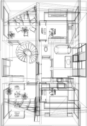
HVAC Load Calculation Example: A Missouri Residential Project

This residential HVAC load calculation example shows what to expect from a professional service: calculated heating and cooling requirements, equipment evaluation, and documents prepared for the installation team. The recent project illustrates how those parts fit together.
ProCalcs recently completed a residential design package for a Missouri home. Its final records connect the home’s load analysis with equipment selection and a documented air-distribution layout.
This example explains the design outputs. Installation performance and energy savings were not measured in the records reviewed here.
HVAC load calculation example: heating and cooling loads
Manual J calculates the home’s heating and cooling requirements. Manual S uses those results and manufacturer performance data to evaluate equipment. The figures below are reproduced from the package’s Manual S compliance summary, which carries the load values forward for equipment comparison.
| Report item | Project value |
|---|---|
| Sensible cooling load | 22,856 Btu/h |
| Latent cooling load | 6,597 Btu/h |
| Total cooling load | 29,453 Btu/h |
| Heating load | 46,346 Btu/h |
| Design airflow used in the equipment evaluation | 1,220 CFM |
Sensible cooling addresses temperature. Latent cooling addresses moisture removal. Their combined total describes the cooling requirement evaluated for the project’s design conditions. Heating is evaluated separately at winter design conditions.
These figures apply to this home. They are not a sizing guide for another property with similar floor area.
Load calculations and equipment capacity are different numbers
The report does not simply convert the cooling load into a nominal equipment label. It compares the selected system’s performance with the calculated requirements at the project’s design conditions.
For this project, the selected system is a nominal 3-ton split air-source heat pump. The report lists cooling capacity of 33,850 Btu/h, including 24,880 Btu/h sensible capacity and 8,970 Btu/h latent capacity, at the evaluated conditions.
It also identifies supplemental heating requirements. That is an important part of the example: the selected heat pump is not presented as independently covering the full winter design heating load.
Manual J load calculations and Manual S equipment selection answer related but different questions: what does the home need, and which equipment meets those needs? A Manual S summary may repeat the load figures, but it does not replace the Manual J load-calculation report. If a reviewer requests Manual J, identify the load-report section in your package or ask the design team to point you to it. Equipment selection should be confirmed as part of the agreed project scope rather than assumed to be included in every load-calculation request.
Review the inputs and decisions before finalizing
The project discussion adds context behind the reports. The designer recorded completing an information-request call, then speaking with the client about the selected HVAC equipment and the outside-air duct included in the design.
An energy recovery ventilator (ERV) was discussed as an option. The client chose not to add one at that stage and indicated that it might be considered later. This describes a project decision, not a general statement about ventilation requirements for other homes.
The designer also recorded a planned window U-factor update before preparing the final documents. That detail illustrates why construction inputs deserve attention during the design process. The discussion does not show the previous and revised U-factors or establish how much the loads changed.
Turn the analysis into an airflow plan
The final mechanical drawings show the planned distribution of air, with room supply runs labeled by airflow and duct size.
In the master bedroom, four 4-inch supply runs are labeled 39, 40, 48 and 50 CFM. A pantry branch is labeled 18 CFM with a 3-inch duct. These examples show that the design documents assign different targets to different locations.
Return-air and transfer-grille arrangements are also shown. This makes the handoff more useful than a whole-house equipment size alone: the installation team can review how the planned air distribution relates to the rooms.
These are design targets, not field measurements. The installed system still requires coordination and balancing.
One project detail: RHEIA duct design
This home’s supply layout uses RHEIA ductwork. The mechanical drawings show the planned routing, manifold details, and assemblies for 3- and 4-inch RHEIA branches. They also include instructions referencing RHEIA Verify during commissioning.
That is the duct-system solution documented for this project. Other homes may need a different layout or distribution approach. The common starting point is the building’s heating and cooling requirements.
Learn more about RHEIA duct design if you are considering that system.
What the complete project package contained
For this project, the final documentation brought together the load calculations, equipment selection, duct layout and supporting energy documentation.
This is a broader design package than a load calculation alone. Customers should confirm the documents included in their quote: load calculations, equipment selection, duct design and energy documentation serve related but different purposes.
The documented result is a completed design handoff. The records reviewed do not establish permit approval, installation time, measured comfort improvement or energy savings.
Request calculations for your project
If you need residential HVAC load calculations, send ProCalcs your plans or a dimensioned sketch, the project location, and a description of the work. Include any known construction specifications and written requirements you have received so the team can identify the scope to quote.
Explore our residential Manual J service or request a project-specific quote.